This is the floppy format that was originally used for T98-Next. It has been superceded by NFD r1, but the emulator remains compatible with both, and NFD r0 images remain more common in collections.
FIVEC will read this format, but saves all NFD images in r1, as the r0 format is significantly different (and depreciated)
This format was documented in detail by the original developer, and is thus relatively well understood. You can find his notes (in Japanese) here. Below, are the annotated notes once translated to English:
2001/01/22 LED
□ Introduction
This text is a floppy disk image file for the PC9821 emulator T98-Next.
It defines the structure of NFD r0 format. Freely used for data analysis, tool development, etc.
please.
□ About structure
The structure of NFD format is roughly divided into a header part and a data part.
The header part exists from the beginning of the file, and the data part exists after that.
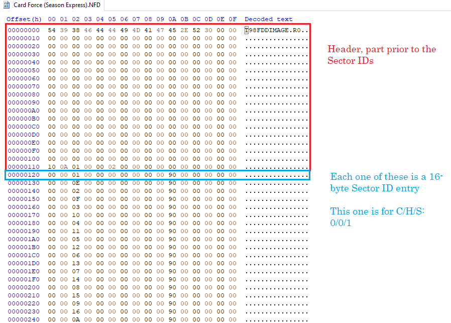
[Header part]
typedef struct {
char szFileID [15]; // Identification ID "T98FDDIMAGE.R0"
char Reserve1 [1]; // Reservation
char szComment [0x100]; // Image comment (ASCIIz)
DWORD dwHeadSize; // Header size
BYTE flProtect; // Other than 0: Write protect
BYTE by Head; // Number of heads
char Reserve2 [10]; // Reservation
NFD_SECT_ID si [163] [26]; // Sector ID (described later)
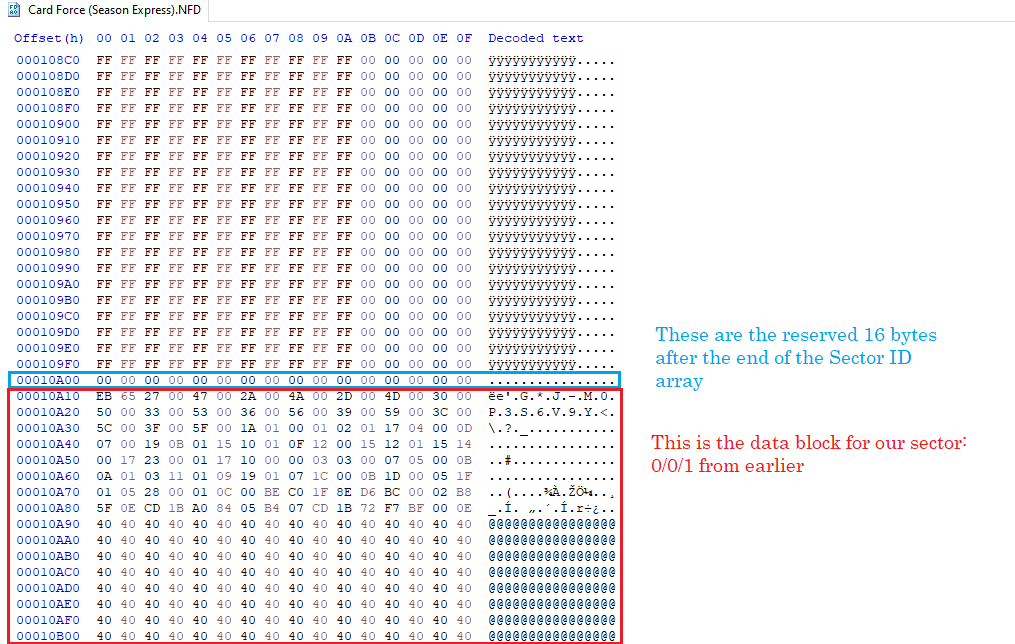
char Reserve3 [0x10]; // Reserve
} NFD_FILE_HEAD, * LP_NFD_FILE_HEAD;
Note) The boundary of the structure is in 1-byte units.
Fill the reserved area with 0
The sector ID (NFD_SECT_ID) is fixed for 163 tracks and 26 sectors.
Has the following structure
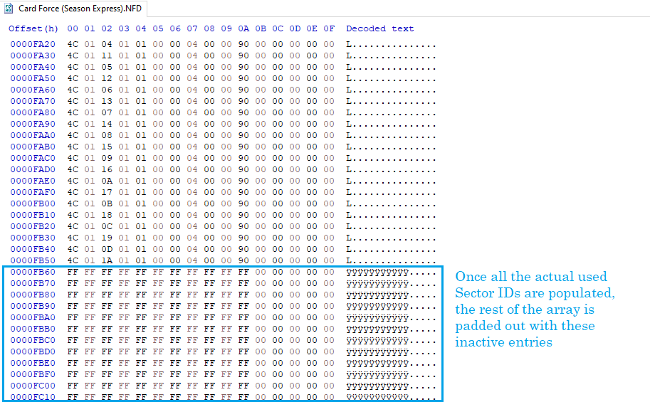
typedef struct {
BYTE C; // C (no sector at 0xFF)
BYTE H; // H
BYTE R; // R
BYTE N; // N (Bytes Per Sector, in 128-shifted format)
BYTE flMFM; // 0: FM / 1: MFM
BYTE flDDAM; // 0: DAM / 1: DDAM
BYTE by Status; // READ DATA (FDDBIOS) result - Always 0x00 for a good read
BYTE by ST0; // Result of READ DATA (FDDBIOS) ST0 -
p.252, bit 2 contains head (So 0x00 for H = 0, 0x04 for H = 1)
Observed bit 1 (US1)
BYTE by ST1; // Result of READ DATA (FDDBIOS) ST1 - Always 0x00 for a good read
BYTE by ST2; // Result of READ DATA (FDDBIOS) ST2 - Always 0x00 for a good read
BYTE by PDA; // Address used by FDD BIOS - See below
char Reserve1 [5]; // Reservation
} NFD_SECT_ID, * LP_NFD_SECT_ID;
Note) The boundary of the structure is in 1-byte units.
Fill the reserved area with 0
The sector ID basically saves the result of READ DATA of FDD BIOS on PC98.
When C is 0xFF, the sector ID is ignored.
For PDA, enter 0x90 when FD is 1.2M, 0x30 when FD is 1.44M, and 0x10 when 640K.
[Data section]
The data part starts from the dwHeadSize byte of the header part from the beginning of the file.
The data part arranges data continuously in the order of sector ID storage.
Emulation Data
The r0 format saves a limited amount of emulation data in the Sector ID (i.e. the status registers: Status, ST0, ST1, ST2), which allow for emulation of intentionally damaged/bad sectors, but not the full
emulation data (i.e. alternative read results) of the r1 format.  If you're curious about what this DISK_RESULT contains (most of the sector ID is that data), then you can see that (in Japanese)
here and here; both of which are excerpted from the PC9800 Technical Data Book Bios 1992

Data Segment Ordering
This is not in standard C/H/S ordering, it's ordered by the sector IDs as they appear in the header, which may be read-based or random.

PDA
The PDA byte appears to mirror the values seen in the FDDType in the FDI/HDI format, at least to a limited extent